Rapid Prototyping for Investment Casting: How to Get a Metal Part Faster
Investment casting is not the fastest manufacturing process. The traditional route — designing the tooling, producing a wax pattern, building the ceramic shell, casting, and finishing — takes weeks. For a new product or a component you have never cast before, that timeline is often necessary. The first pour needs to work, and that takes preparation. But there are situations where you need a metal part faster than that. A design that needs physical validation before full tooling is committed. A small batch of components to test in the field before ramping up production. A replacement part needed urgently while long-lead tooling is being made. For these situations, rapid prototyping offers a practical alternative.
Why Prototyping Matters in Investment Casting
Investment casting tooling is not cheap or quick to change. Once a die or wax injection tool is made, modifying it is costly and time-consuming. If a design flaw only becomes apparent after the first production run, you are looking at tooling rework, lost time, and wasted material. Prototyping before committing to production tooling reduces that risk. A physical part in the right material — not plastic, not a machined approximation, but an actual casting in the specified alloy — gives you real information about how the design performs. You can check fit and function, test surface finish, identify any issues with wall thickness or geometry, and sign off on the design with confidence before the full tooling investment is made.

How Rapid Prototyping Works in Practice
The key to getting a cast metal part quickly is eliminating the time spent on wax injection tooling. Instead of cutting a tool to inject wax patterns, 3D printing is used to produce the patterns directly from the CAD file. This is the step that typically takes weeks in a conventional workflow, and removing it is what makes rapid timelines possible.
3D Printed Patterns
A pattern produced by stereolithography (SLA) or similar additive processes can be printed in hours from a STEP or STL file. The pattern behaves like a wax pattern in the investment casting process — it is coated in ceramic slurry, the shell is built up and cured, and then the pattern is burned out before the metal is poured. Print quality matters here. A poorly printed pattern produces a poor casting. The surface finish of the printed pattern directly affects the surface finish of the cast part, so the choice of printing technology and process parameters is important.
Vacuum Casting for Thin-Walled Parts
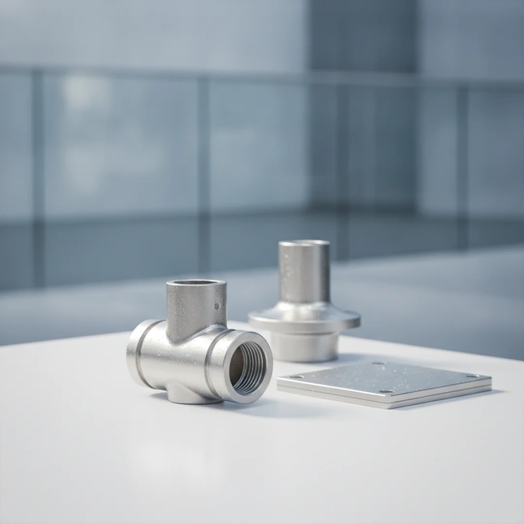
For components with thin walls, fine detail, or complex internal geometry, vacuum-assisted casting reduces the risk of defects. Applying vacuum during the pour draws the molten metal into fine features that gravity alone might not fill reliably. This is particularly relevant for parts like valve bodies, pump components, and fittings where wall sections can be under 3mm and dimensional accuracy is critical.
Finishing and Machining
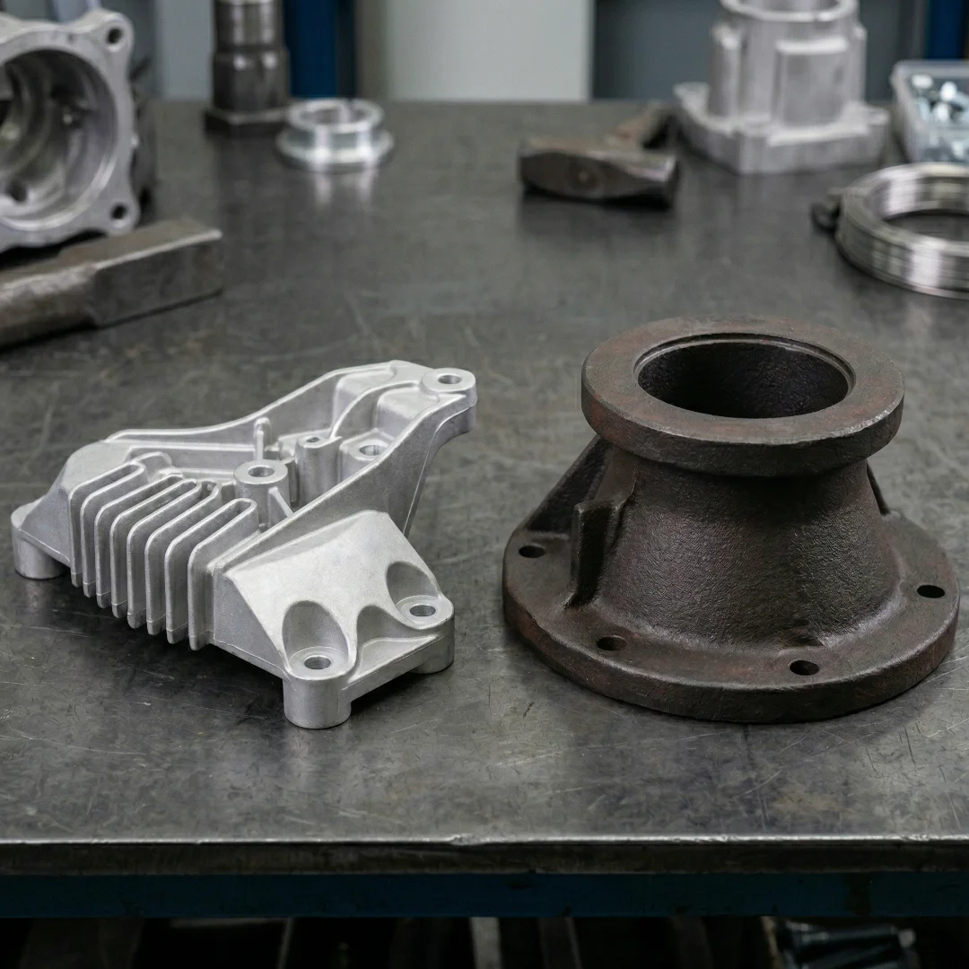
A prototype cast part goes through the same finishing operations as a production part — shot blasting or bead blasting to clean the surface, CNC machining of any critical dimensions or interfaces, and surface finishing as required. The result is a part that represents final production quality, not a rough approximation.
When Rapid Prototyping Makes Sense
Prototyping before full tooling is worth doing when the design is not fully proven and you want to validate it physically before committing to production tooling costs. Even a single prototype that reveals a flaw in the geometry can save significant expense downstream. It also makes sense when you need a small quantity of parts before production tooling is ready. If you have an order to fulfil or a trial to run but the production tooling is still being made, prototype-route parts can bridge the gap. For parts with complex geometry, tight tolerances, or demanding alloys, a prototype run also gives the foundry useful information about how the material and design behave during casting. That knowledge makes the first production run more likely to succeed first time.
When It Does Not Make Sense
If your design is already proven and you are moving directly into production, the additional cost of 3D printed patterns is not justified. Production wax injection tooling is more economical per part at volume. Rapid prototyping is also not the right route if you need very large quantities quickly. The process is suited to small numbers of parts — typically single digits to a few dozen — not high-volume production.
How Long Does It Actually Take?
The honest answer is that it depends on the complexity of the part, the alloy, and what finishing is required. A simple stainless steel component with standard finishing can be ready in under two weeks from receipt of a drawing. A more complex part in a demanding alloy with tight machined tolerances will take longer. A rough guide for a typical prototype component: Pattern printing and DFM review: 2 to 3 days Shell building and casting: 3 to 5 days Finishing, machining, and inspection: 3 to 5 days Total lead time from drawing to finished part: typically 2 to 3 weeks depending on complexity. This is significantly faster than the 8 to 12 weeks that conventional investment casting tooling can take from scratch, but it is worth being realistic — not every part can be turned around in a week, and a foundry that promises that universally is probably overstating things.
| Stage | Typical Duration | What Happens |
|---|---|---|
| Design review and DFM | 1 to 2 days | We review your STEP file and flag any issues before work starts |
| Pattern production | 1 to 2 days | 3D printed resin pattern produced directly from your file |
| Shell building | 2 to 4 days | Ceramic shell built up in layers around the pattern and cured |
| Dewax and casting | 1 to 2 days | Pattern removed, metal poured into the shell |
| Finishing and machining | 3 to 5 days | Shot blasting, CNC machining of critical features, surface finishing |
| Inspection and dispatch | 1 day | Dimensional check and visual inspection before shipping |
What to Send Us to Get Started
The more information you can share upfront, the faster we can review your design and give you an accurate timeline and quote. A STEP or IGES file of the part is the starting point. Alongside that, it helps to know the required alloy, the critical dimensions and tolerances that must be met, the surface finish requirement, and how many parts you need in this initial run. If the part has been cast before or you have existing production samples, letting us know helps us understand what level of quality you are targeting. We will review the design for manufacturability and flag anything that might cause problems in casting before any work starts. This DFM review is a normal part of the prototyping process and is worth taking seriously — it is much easier to address a wall-thickness issue in the CAD file than after the first pour.